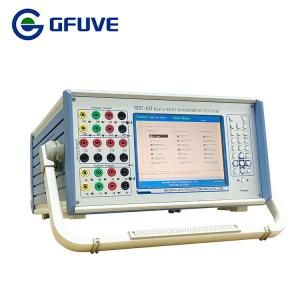
TEST-630 Multi Phase Protection Relay Secondary Current Injection Test Equipment
The multiple protection function of today’s protection relay systems requires a new level of sophisticated test hardware and software to completely analyse the operation of the unit in a real life situation. Every facet of relay testing can be handled with the comprehensive line of relay test equipment from GFUVE.
Relay and substation test system. TEST-630. Our aim is to make simpler the complex task of 3-phase relay testing. Our comprehensive and intuitive relay software speeds up testing times with a vast library of pre-defined test regimes or manual operation. A range of current and voltage channels options, displays and added functions are all packed in to a powerful but light weight unit.
TEST-630 is designed with fuse on the mains supply and electronic protection for overload on the current (open circuit) or voltage outputs(short circuit), with immediate isolation of the output and alarm indication. Also diagnostic message for the setting of wrong data, mistakes on the input etc. There's also electronic protection in case of counter-feed of voltage output, if any incorrectness happen, the alarm light shall flash. And Overheat LED indicator shall flash for Protection against over-temperature, on all outputs.
Differential
is suitable for use the 6 output current channels' relay tester, which is applied on transformer, generator and bus bar etc. differential protection equipment test. Because of adopting the 6 currents output, it realizes the two sides three phases test between relay tester and relay equipment.
Inverse time overcurrent
This module realizes the directional over-current test and non-directional over-current test. This module also include: testing positive sequence, negative sequence and zero sequence instantaneous time over-current,
over-heat protection inverse time over-current or the customized “Current/Time” operation characteristic.
TEST ITEM
- Differential relay
- Harmonic test
- Differential protection
- Distance protection
- Zero sequence protection
- Setting group test
- State sequence
- Synchronization test
- U/I test
- DC test
- Impedance characteristics
- Power direction test
- I-T test
- Special test
- Oscillation test
- Metering instrument
- Hardware checkout
- Low Voltage protection
- Fault Recurrence

PARAMETERS
| Electrical parameters |
| Power voltage | AC220V±10% or AC110V±10%, 50/60Hz±10% |
| Time measurement | 0.1ms-999999.999s |
| AC current output |
| Phase current output (effective value) | 6 x 0-30A |
| Maximum power output | 260VA/phase |
| Maximum parallel current output (effective value) | 0-180A |
Long-term allowable working value of phase current
(effective value) | >10A |
| Allowable working time of maximum current | >11s |
| Accuracy class | <±0.2% |
| AC voltage output |
| Phase voltage output (effective value) | 6 x 0-130V |
| Line voltage output (effective value) | 0-260V |
| Maximum power output | 70VA/phase |
| Accuracy class | <±0.2% |
| DC current output |
| Output range | -10 to 10A or 6 x 0 to ±10A |
| Maximum power output | 200VA |
| Accuracy class | <±0.2% |
| DC voltage output |
| Output range | 0-300V or 6 x 0 to ±130V |
| Maximum output power | 130VA |
| Accuracy class | <±0.2% |
| Binary input |
| Idle contact | 1-20mA, 24V (DC) |
| Electric potential contact | 250V/0.5A (DC) |
| Binary output |
| Idle contact | 250V/0.5A (DC) |
| Rated output |
| Frequency error | <±0.01Hz |
| Phase error | <±0.1° |
| Waveform distortion | <±0.3% (fundamental wave) |
| Time error | <40µs |
| Output frequency | 0-1050Hz |
| Superposed harmonic wave | 0-21times |
PHOTO